Here are some notes on my approach to levitating magnets. I am using the method of suspending a small permanent magnet between two diamagnetic plates. This method of diamagnetic levitation does not involve electrical power of any sort. Nor does it use low temperatures or rotating magnetic fields.
My focus is to experiment with some of the variables involved in obtaining a stable levitation. My first experiments use bismuth as the diamagnetic material. I will provide details below but for those of you who are already familiar with this effect, I will begin with a summary of some useful things I have found out so far:
There are many other websites that contain information about this phenomenon and also have suggestions on how to do this at home.
See the following sites for a basic explanation of how to levitate a magnet.
- http://scitoys.com/scitoys/scitoys/magnets/suspension.html
- http://www.fieldlines.com/other/diamag1.html
- http://www.magnetlevitation.com
Beginning with the knowledge obtained from the above-mentioned sites, I designed my own rig. This design allows me to easily change the shape and strength of the suspending magnetic field. It also provides a way to make fine adjustments to the spacing of the elements of the rig.
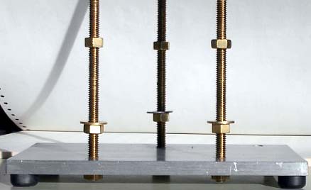
The first photo shows the bare stand which is three brass rods mounted in an aluminum plate.
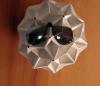
I had never seen bismuth before. It is a metallic element which is not quite as dense as lead and is white with a pinkish tinge. Bismuth is crystalline and rather brittle and it expands as it solidifies. It amalgamates with lead so I embedded tinned copper wires into the casting so that I could support the upper repeller. It is important to keep the copper away from the center of the casting or else make sure it is deeply embedded because copper is not diamagnetic. The casting was done in the bottom of a pop can as described in the above references. This photo shows the upper repeller on the stand.
French-fry your bismuth
There are some tricks that will make it easier to cast the bismuth repellers. The bismuth as obtained is in the form of black spheres. These spheres need to be melted together in order to form a flat surface for repelling the magnet. When the bismuth is melted, the black oxide (dross) floats to the top of the liquid metal where it can be scraped off. But more oxide begins to form immediately due to air contacting the liquid metal surface. If you put some Crisco or cooking oil onto the bismuth and then melt it, the oil floats to the top of the metal and seals out the oxygen. Also, the dross floats in the oil and is easily removed. Thus you can obtain very clean and shiny bismuth for casting.
Another trick is to melt the bismuth in place. To do this, cut some openings in the side of the pop can, put the bismuth shot and oil into the well of the can, and use a small propane torch to heat it from underneath. Once it is molten, try to cool it differentially from one side. That is, keep one side warmer while the other side solidifies. This has the advantage of providing one spot where the upwelling will occur. Bismuth is an unusual material because it expands when it solidifies. This means that the mirror-smooth surface of a puddle of liquid bismuth will be overlaid with a messy upwelling as it cools. If you can keep the upwelling on one edge, then the rest of the piece can remain flat and highly reflective. There will be crystal patterns in the surface but they will not detract from its reflectivity. The finish will be flatter and more perfect than that which can be obtained by polishing. It is nice to have the mirror finish because the reflective surface helps to display the floating magnet. Warning: Such a surface is very easily scratched by even a very soft cloth. So to retain a flawless finish, DON'T TOUCH. Of course, you can always remelt the bismuth and try again.
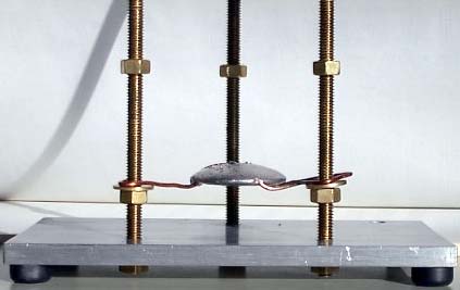
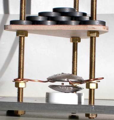
This photo shows a magnet levitating in the rig. The rig makes it easy to experiment with variations of the positions of the components. The lower repeller is sitting on a white plastic bottle cap. This makes it easier to remove and adjust. The mirror finish of the lower bismuth repeller makes the air gap between the magnet and the bismuth very obvious. Notice that I am using just one cube magnet on the top deck to provide the magnetic field that will counteract the weight of the levitating magnet. A cheaper magnet can be used but the deck will need to be lowered somewhat.
Potential Energy Graphs
Here is an easy way to understand what is going on. Let's look at the potential energy of the tiny cube magnet. Without the bismuth repellers, a graph of height (horizonal) versus potential energy (vertical) looks like this.
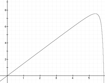
Potential energy rises linearly as the magnet is raised. But when it gets near the supporting magnet, the pull causes a rapid drop in potential energy. Notice that the top of the "knee" on the graph is smoothly rounded so that there is no position which is stable. The top of the curve corresponds to the familiar "neutral" feeling when forces just balance.
The diamagnetism of bismuth delivers a small repulsion when a magnet comes near. A single repeller can create a small stable region if it is placed near the point of maximum potential energy. The following graph shows the use of a lower repeller.
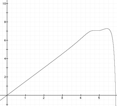
According to the graph, the magnet will be stable in a region where almost all of its weight is cancelled by the suspending magnetic field so that the repeller can deliver the remaining push for levitation. This region exists but is very touchy. By using both lower and upper repellers, the following graph can be obtained.
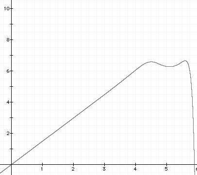
If the magnet rises, it is pushed down by the upper repeller. If the magnet moves down, it is pushed up by the lower repeller.
The magnet can also float freely below the upper repeller without the lower repeller. But if the magnet ventures too far below the repeller, it falls because it reaches a weaker part of the suspending magnetic field which cannot support the entire weight of the magnet.
Spread out your field
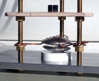
I found that the gap between the upper and lower bismuth repellers can be increased if the supporting magnetic field is spread out. One way to do this is to use many magnets with their poles all aligned in the same direction. I made this magnet stack by gluing the first level of magnets onto the plywood board. (The magnets must be glued because otherwise they will flip due to repulsive forces.) Warning: cheap ceramic magnets such as those shown may not deliver uniform fields. Each magnet can be tested by using some "magnetic viewing film", available from http://www.wondermagnet.com
Using this magnet stack, I can obtain a gap about 1mm above and 1mm below a levitating magnet. So the effect is most dramatic if I use small magnets. I'm floating 2.3mm NdFeB cubes (gold-plated).
This arrangement suspends a magnet in a fairly sizeable potential well in 3-space. The stable region is a cylindrical volume 4mm high and about 40mm in diameter. Vertical period of oscillation is about 0.7 sec, horizontal period is about 1 second. (3-D Lissajous figures!) So it can be used as a very sensitive detector of magnetic properties of materials. For instance, by bringing a pencil point near the levitating magnet, I have found that pencil "lead" is paramagnetic. That is, it slightly attracts both poles of a magnet. This is surprising because pure graphite is supposed to be diamagnetic and thus repel like the bismuth does. Perhaps it is the clay binder in the pencil lead that causes the effect.
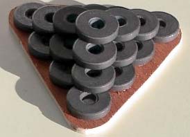
Using this broad field, I can put two cubes into the levitator simultaneously. Since the levitated magnets have their poles aligned, they repel each other. The repulsion is balanced by the gradients in the field so that two magnets will lie equidistant from the supporting field's central axis. (14mm separation) I can even put three magnets into the device if I'm careful. But they lie at the vertices of an equilateral triangle 23mm apart -- just inside the edges of the bismuth repellers. So four magnets are out of the question with the current repellers.
Future Work
How thick does the repeller need to be?. Can I increase the gap by using thicker bismuth? Can the bismuth be shaped to act like a "lens" to improve the properties of the stable zone? Can I modify the supporting field to further improve the stable zone? What about putting a steel plate or magnets beneath the rig to make the magnetic field more uniform?
Another question that comes up is, "Can a piece of soft iron be used in place of the levitating magnet?" Soft iron responds to a magnetic field by becoming a temporary magnet itself. But its magnetic character depends upon the external field. So a piece of soft iron in the rig would certainly not work against the lower repeller since its strength would drop as its position drops so that the repulsion would lessen as well. But there might be some hope using just the upper repeller. I have not yet done this experiment.
I will post my answers to these and other questions as I continue experimentation.
Although the diamagnetic effect is small, it provides some interesting effects. I can even feel the reduced friction when putting a strong magnet against the surface of the bismuth. Practical uses may be found for this effect.
You can contact me with questions or comments.